My efforts to persuade two early 1970’s Burroughs gas plasma display panels to work.
In 1971 the Burroughs Corporation of Detroit announced Neon-based Self Scan gas plasma panels as an innovative successor to cathode ray tube technologies. The Self Scans required less power, had no deflection coils, had simplified electronic circuitry, and displayed an attractive sharp, stable character set in monochrome orange. However they still required relatively high voltage to energise the tiny gas tubes.
Unlikely Partners
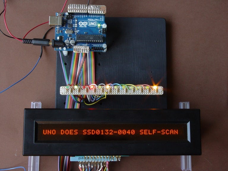
This is a 1976 Burroughs SSD0132-0040 Self Scan panel. It displays one row of 32 characters. I had the greatest success with this panel, after I connected it to a present day Arduino Uno microcontroller…
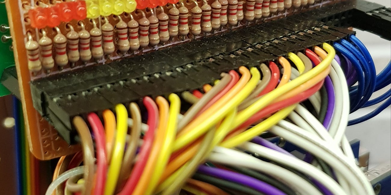
Everyone loves a set of blinky lights. Well at least, I do. I have a good excuse for the lights in this picture. These LEDs help me to diagnose - to understand the “handshaking” logic sequences between the Uno and the SSD. To help further, I can slow the process right down to single steps by introducing delays to the Uno’s code. It turns out that most of the signals which tell the display how to behave are “ACTIVE LOW”. So for example, when the SSD wants to say to the UNO:- “I’m ready for the next 6 bits of character data”, it sets pin 7 to (near) zero volts, not, as you might have expected, +3.3 or 5v.
I love the idea of the Uno reaching back into 1976 to bring this SSD to life. That said, the Uno still needs a little help from a DC 250 volt power supply, to energise the plasma display. The 250 volts DC input is the wire shrouded in red heat shrink tube on tag 10 of the lower connector. Don't try this at home folks unless you are really confident with high voltages and safety precautions.
Connections
These are the connections I used to make the SSD active.
1, A, 2, B. 3, C - 6 bit data, which I had in reverse order on my first attempt.
8 - BLANK UNO → SSD
F - ACK SSD → UNO (active low)
5 - RESET UNO → SSD (active low)
7 - READY SSD → UNO (active low)
D - LOAD → UNO → SSD (active low)
L - GND
J - +5 volts
10 - +250 volts
4 -12 volts
TD700
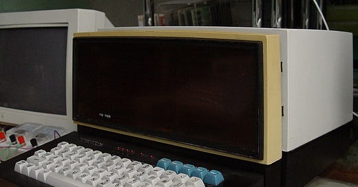
I’ve had less success with the SSD’s big brother. This is a TD700 DL4 Self Scan plasma display from 1973 which displays 8 rows of 32 characters.
The plasma display panel is detached and separate from the terminal case containing the circuit cards, cage and backplane. It rests on its own supporting feet and is connected by means of an unwieldy multicore cable. This arrangement allows the display panel and keyboard to be used 18 inches or so away from the terminal case.
I started by replacing 2 corroded capacitors on cards "A" and "T" in the control unit cage.
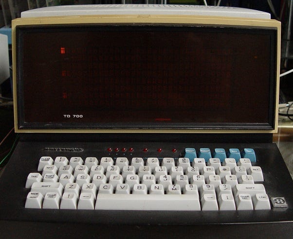
After 4 days spent gingerly notching up the power supply using my trusty variac, trying not to pop the aged PSU capacitors, I achieved a display cursor with ghosting on rows 4 and 7. You can just make it out, top left of display area in the next picture. The faint pixels shown up by the cursor occur in the same positions across the row. I hope this will be a resolvable logic or driver issue in the self-scan control card, rather than a write-off self-scan module…
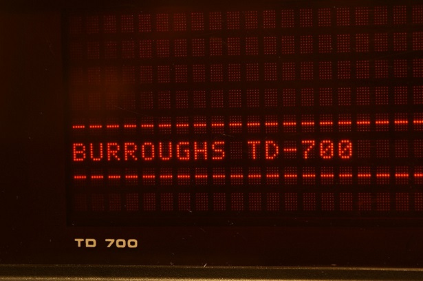
A working display looks like this…
However, after a short while my experiment had to be rapidly abandoned. The line voltage had suddenly jumped to 600 volts DC. I decided at this point not to risk the aged capacitors any further, but to build the TD700 a brand new external supply.
Wire Wrap
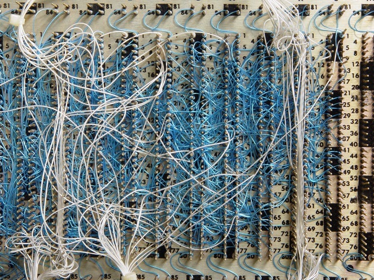
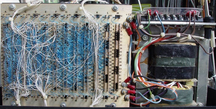
The TD700’s wire wrap backplane is a wonder to behold. No printed circuit copper trace address bus or data bus here…
The aged PSU capacitors are tucked behind the mains transformer, together with other metal canisters which I’m fairly sure are rectifiers…
The transformer frame incorporates a useful set of test points for 5.1v, 12v, -12v, 30v and -250v. Oddly, these points were all up to required values when the variac was supplying only 110 volts AC. This TD700’s identity plate is stamped for 240 volts!
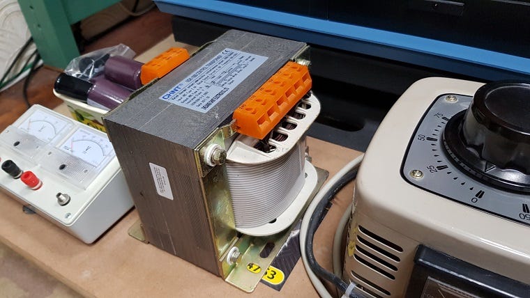
I sourced an external panel transformer whose outputs can easily be adapted to correspond with the TD700’s test point requirements, whilst at the same time capable of supplying the relatively high current requirement. It’s on a trolley because it’s heavy…
Having gathered together the capacitors, voltmeters and other required components, sadly for now the PSU build is low down on my “To Do” list. That will have to be a story for another day.
Coming soon, weather permitting, is “The Station” my garden railway picture story.
You might like one or more or my other posts: -
Covert Carer
Why…? My first COPING WITH CARING Substack post outlined that I’m unpaid care giver for two vulnerable ladies, my mother aged 99 and my wife aged 67. Care giving creates a new, unexpected, hectic chapter in the carer’s life. Familiar home routines are scrambled, Sky Sports is cancelled, and “want-to-do” lists are consigned to the waste bin.
Nearly Talking of Robots
Whilst I don’t have a great deal of time to devote to them nowadays my robot and train projects continue (slowly) as my occasional escape from care giving. Last night, I became so frustrated with my inability include a short video clip in a reply to a note (most likely operator error), that I decided to create this new post.
The Summerhouse
We were startled by the bang. A toughened pane in a rotting frame just shattered, scattering a thousand glistening diamonds to the ground. “Help me!” it screamed. “Please don’t neglect me into decay and nothingness…” I’m so glad we didn’t. I made it better. Roof re-membraned. Wood re-coated. Oversized doors from eBay cut to fit. Windows of clear…
Helpful Things
There are simple low tech items that can make a big difference when you are a carer. Here are a few I use. This whistle-stop tour is not intended in any way as promotional… Plug-in Night Light A plug-shaped light which fits in a mains socket to light automatically when darkness falls. The gentle glow in bedroom and hall provides a safer, comforting en…
Can I Trust the NHS?
“Terrible Culture of Blame" When did:- “Don't worry, we will absolutely keep you safe" ¹ Change to:- “Don't worry, if we accidentally kill you, we will definitely learn lessons from it". In March 2016 then UK Health Secretary Jeremy Hunt said “It is a scandal that every week there are potentially 150 avoidable deaths in our hospitals and it is up to us a…
Caring
In today's society, I wonder how many people muse:-, “Never did I dream that in retirement I would be an unpaid carer”. I do. I've realised that Caring is not just about physical help, there are just as many psychological challenges. Whilst personal, I'll make these posts supportive rather than excessively self- obsessed. I'll mention subjects ranging…


